Displaying a Point Cloud Using Scene Depth
Present a visualization of the physical environment by placing points based a scene’s depth data.
Overview
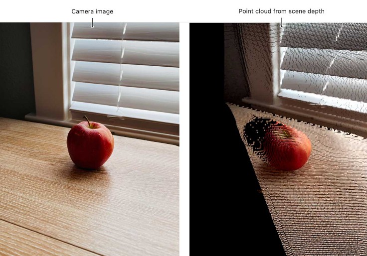
Depth Cloud is an app that uses Metal to display a camera feed by placing a collection of points in the physical environment, according to depth information from the device’s LiDAR Scanner. For every distance sample in the session’s periodic depth reading (depthMap), the app places a virtual dot at that location in the physical environment, with the final result resembling a point cloud. Depth Cloud colors the cloud according to ARKit’s camera image (capturedImage).
For every entry in the depth map — and therefore, for every dot in the cloud — the sample app checks the corresponding pixel in the camera image and assigns the pixel’s color to the dot. When the user views the point cloud straight on, the app’s display appears nearly identical to a camera feed. To demonstrate the cloud’s 3D shape, the sample app continuously rotates the cloud to change its viewing angle with respect to the user.
The following figure illustrates a point cloud from a single frame of data, rotated on the y-axis to reveal a dark area behind the apple where the current sensor readings lack color and depth information.

The app cycles through depth confidence values (see confidenceMap), enlarges the depth buffer, and toggles ARKit’s smooth depth option (smoothedSceneDepth). By applying the user’s selections to the point cloud live, the user can see the difference that the settings make throughout the experience.
- Note: WWDC20 session 10611: Explore ARKit 4 references a prior version of this sample app that accumulates points in a cloud. For the original version of the app as shown in the session, clone the initial commit from the Git repository in the download’s root folder.
For a practical application of ARKit’s depth data, see the fog sample.
Set Up a Camera Feed
To display a camera feed, the sample project defines a SwiftUI Scene whose body contains a single window. To abstract view code from window code, the sample project wraps all of its display in a single View called MetalDepthView.
@main
struct PointCloudDepthSample: App {
    var body: some Scene {
        WindowGroup {
            MetalDepthView()
Because Depth Cloud draws graphics using Metal, the sample project displays the camera feed by defining custom GPU code. The sample project accesses ARKit’s camera feed in its ARReceiver.swift file and wraps it in a custom ARData object for eventual transfer to the GPU.
arData.colorImage = frame.capturedImage
Ensure Device Support and Start a Session
Devices require the LiDAR Scanner to access the scene’s depth. In the depth-visualization view’s body definition, the app prevents running an unsupported configuration by checking if the device supports scene depth.
if !ARWorldTrackingConfiguration.supportsFrameSemantics([.sceneDepth, .smoothedSceneDepth]) {
    Text("Unsupported Device: This app requires the LiDAR Scanner to access the scene's depth.")
To separate data acquisition from its display, the sample app wraps ARKit calls in its ARProvider class.
@ObservedObject var arProvider: ARProvider = ARProvider()!
The AR provider runs a world-tracking configuration and requests information about the scene’s depth by configuring the scene-depth frame semantics (see sceneDepth and smoothedSceneDepth).
let config = ARWorldTrackingConfiguration()
config.frameSemantics = [.sceneDepth, .smoothedSceneDepth]
arSession.run(config)
Access the Scene’s Depth
In response to the configuration’s scene-depth frame semantics, the framework defines the frame’s depthMap properties of sceneDepth and smoothedSceneDepth on the session’s currentFrame.
func session(_ session: ARSession, didUpdate frame: ARFrame) {
    if(frame.sceneDepth != nil) && (frame.smoothedSceneDepth != nil) {
        arData.depthImage = frame.sceneDepth?.depthMap
        arData.depthSmoothImage = frame.smoothedSceneDepth?.depthMap
Because the sample project draws its graphics using Metal, the app’s CPU code bundles up data that its GPU code needs to display the experience. To model the physical environment with a point cloud, the app needs camera capture data to color each point and depth data to position them.
The sample project positions each point in GPU code, so the CPU side packages the depth data in a Metal texture for use on the GPU.
depthContent.texture = lastArData?.depthImage?.texture(withFormat: .r32Float, planeIndex: 0, addToCache: textureCache!)!
The sample project colors each point in GPU code, so the CPU side packages the camera data for use on the GPU.
colorYContent.texture = lastArData?.colorImage?.texture(withFormat: .r8Unorm, planeIndex: 0, addToCache: textureCache!)!
colorCbCrContent.texture = lastArData?.colorImage?.texture(withFormat: .rg8Unorm, planeIndex: 1, addToCache: textureCache!)!
Convert Camera Data
In the pointCloudVertexShader function (see the sample project’s shaders.metal file), the sample project creates a point for every value in the depth texture and determines the point’s color by sampling that depth-texture value’s position in the camera image. Each vertex calculates its x and y location in the camera image by converting its position in the one-dimensional vertex array, to a 2D position in the depth texture.
uint2 pos;
// Count the rows that are depth-texture-width wide to determine the y-value.
pos.y = vertexID / depthTexture.get_width();

// The x-position is the remainder of the y-value division.
pos.x = vertexID % depthTexture.get_width();
The system’s camera-capture pipeline represents data in YUV format, which the sample project models using a luminance map (colorYtexture) and a blue versus red chromaticity map (colorCbCrtexture). The GPU color format is RGBA, which requires the sample project to convert the camera data to display it. The shader samples the luminance and chromaticity textures at the vertex’s x, y position and applies a static conversion factor.
constexpr sampler textureSampler (mag_filter::linear,
                                  min_filter::linear);
out.coor = { pos.x / (depthTexture.get_width() - 1.0f), pos.y / (depthTexture.get_height() - 1.0f) };
half y = colorYtexture.sample(textureSampler, out.coor).r;
half2 uv = colorCbCrtexture.sample(textureSampler, out.coor).rg - half2(0.5h, 0.5h);
// Convert YUV to RGB inline.
half4 rgbaResult = half4(y + 1.402h * uv.y, y - 0.7141h * uv.y - 0.3441h * uv.x, y + 1.772h * uv.x, 1.0h);
- Note: For brevity, the sample project demonstrates YUV to RGB conversion inline. To see an example that extracts static conversion factors to a 4 x 4 matrix, see the Metal AR article.
Set Up the Point Cloud View
To display a camera feed by using a point cloud, the project defines a UIViewRepresentable object, MetalPointCloud, which contains an MTKView that displays Metal content.
struct MetalPointCloud: UIViewRepresentable {
    var mtkView: MTKView
The project inserts the point cloud view into the view hierarchy by embedding it within the MetalDepthView layout.
HStack {
    Spacer()
    MetalPointCloud(mtkView: MTKView(), arData: arProvider, confSelection: $selectedConfidence, scaleMovement: $scaleMovement)
        .zoomOnTapModifier(height: geometry.size.width / 2 / sizeW * sizeH, width: geometry.size.width / 2, title: "")
As representable of UIView, the Metal texture view defines a coordinator, CoordinatorPointCloud.
func makeCoordinator() -> CoordinatorPointCloud {
    return CoordinatorPointCloud( mtkView: mtkView, arData: arData, confSelection: $confSelection, scaleMovement: $scaleMovement)
}
The point cloud coordinator extends MTKCoordinator, which the sample shares across its other views that display Metal content.
final class CoordinatorPointCloud: MTKCoordinator {
As an MTKViewDelegate, MTKCoordinator handles relevant events that occur throughout the Metal view life cycle.
class MTKCoordinator: NSObject, MTKViewDelegate {
In the UIView representable’s makeUIView implementation, the sample project assigns the coordinator as the view’s delegate.
func makeUIView(context: UIViewRepresentableContext<MetalPointCloud>) -> MTKView {
    mtkView.delegate = context.coordinator
MTKView sets up a display link for the sample project’s preferred frames per second.
mtkView.preferredFramesPerSecond = 60
As a result, the display link calls the Metal coordinator’s draw in view implementation 60 times per second.
override func draw(in view: MTKView) {
    content = arData.depthContent
    let confidence = (arData.isToUpsampleDepth) ? arData.upscaledConfidence:arData.confidenceContent
    guard arData.lastArData != nil else {
Display the Point Cloud with GPU Code
The sample project draws the point cloud on the GPU. The point cloud view packages up several textures that its corresponding GPU code requires as input.
encoder.setVertexTexture(content.texture, index: 0)
encoder.setVertexTexture(confidence.texture, index: 1)
encoder.setVertexTexture(arData.colorYContent.texture, index: 2)
encoder.setVertexTexture(arData.colorCbCrContent.texture, index: 3)
Similarly, the point cloud view packages up several calculated properties that its corresponding GPU code requires as input.
encoder.setVertexBytes(&pmv, length: MemoryLayout<matrix_float4x4>.stride, index: 0)
encoder.setVertexBytes(&cameraIntrinsics, length: MemoryLayout<matrix_float3x3>.stride, index: 1)
encoder.setVertexBytes(&confSelection, length: MemoryLayout<Int>.stride, index: 2)
To call into the GPU functions that draw the point cloud, the sample defines a pipeline state that queues up its pointCloudVertexShader and pointCloudFragmentShader Metal functions (see the project’s shaders.metal file).
pipelineDescriptor.vertexFunction = library.makeFunction(name: "pointCloudVertexShader")
pipelineDescriptor.fragmentFunction = library.makeFunction(name: "pointCloudFragmentShader")
On the GPU, the point cloud vertex shader determines each point’s color and position on the screen. In the function signature, the vertex shader receives the input textures and properties sent by the CPU code.
vertex ParticleVertexInOut pointCloudVertexShader(
    uint vertexID [[ vertex_id ]],
    texture2d<float, access::read> depthTexture [[ texture(0) ]],
    texture2d<float, access::read> confTexture [[ texture(1) ]],
    constant float4x4& viewMatrix [[ buffer(0) ]],
    constant float3x3& cameraIntrinsics [[ buffer(1) ]],
    constant int &confFilterMode [[ buffer(2) ]],
    texture2d<half> colorYtexture [[ texture(2) ]],
    texture2d<half> colorCbCrtexture [[ texture(3) ]]
    )
{ // ...
The code bases the point’s world position on its location and depth in the camera feed.
float xrw = ((int)pos.x - cameraIntrinsics[2][0]) * depth / cameraIntrinsics[0][0];
float yrw = ((int)pos.y - cameraIntrinsics[2][1]) * depth / cameraIntrinsics[1][1];
float4 xyzw = { xrw, yrw, depth, 1.f };
The point’s screen position is a product of its world position and the argument projection matrix.
float4 vecout = viewMatrix * xyzw;
The vertex function outputs the point’s screen position, along with the point’s color as a converted RGB result.
out.color = rgbaResult;
out.clipSpacePosition = vecout;
The fragment shader receives the vertex function output in its function signature.
fragment half4 pointCloudFragmentShader(
    ParticleVertexInOut in [[stage_in]])
After filtering any points that are too close to the device’s camera, the fragment shader queues the remaining points for display by returning the color of each vertex.
if (in.depth < 1.0f)
    discard_fragment();
else
{
    return in.color;
Change the Cloud’s Orientation to Convey Depth
As the user views the point cloud straight on, it appears visually equivalent to the 2D camera image. But, when the sample app rotates the point cloud slightly, the 3D shape of the point cloud becomes apparent to the user.

The point cloud’s screen position is a factor of its projection matrix. In the sample project’s calcCurrentPMVMatrix function (see MetalPointCloud.swift), the function sets up a basic matrix.
func calcCurrentPMVMatrix(viewSize: CGSize) -> matrix_float4x4 {
    let projection: matrix_float4x4 = makePerspectiveMatrixProjection(fovyRadians: Float.pi / 2.0,
                                                                      aspect: Float(viewSize.width) / Float(viewSize.height),
                                                                      nearZ: 10.0, farZ: 8000.0)
To adjust the point cloud’s orientation with respect to the user, the sample app conversely sets up translation and rotation offsets for the camera’s pose.
// Randomize the camera scale.
translationCamera.columns.3 = [150 * sinf, -150 * cossqr, -150 * scaleMovement * sinsqr, 1]
// Randomize the camera movement.
cameraRotation = simd_quatf(angle: staticAngle, axis: SIMD3(x: -sinsqr / 3, y: -cossqr / 3, z: 0))
The sample project applies the camera pose offset to the original projection matrix before returning the adjusted result.
let rotationMatrix: matrix_float4x4 = matrix_float4x4(cameraRotation)
let pmv = projection * rotationMatrix * translationCamera * translationOrig * orientationOrig
return pmv
Enlarge the Depth Buffer
ARKit’s depth map contains precise, low-resolution depth values for objects in the camera feed. To create the illusion of a high-resolution depth map, the sample app offers UI to enlarge the depth map using Metal Performance Shaders (MPS). By filling in gaps in the framework’s depth information, the enlarged depth buffer creates the illusion of more depth information in the scene.

The sample project uses MPS to enlarge the depth buffer; see the ARDataProvider.swift file. The ARProvider class initializer creates a guided filter to enlarge the depth buffer.
guidedFilter = MPSImageGuidedFilter(device: metalDevice, kernelDiameter: guidedFilterKernelDiameter)
To align the sizes of the related visuals — the camera image and confidence texture ����— the AR provider uses an MPS bilinear scale filter.
mpsScaleFilter = MPSImageBilinearScale(device: metalDevice)
In the processLastARData routine, the AR provider creates an additional Metal command buffer for a compute pass that enlarges the depth buffer.
if isToUpsampleDepth {
The AR provider converts the input depth data to RGB format, as required by the guided filter.
let convertYUV2RGBFunc = lib.makeFunction(name: "convertYCbCrToRGBA")
pipelineStateCompute = try metalDevice.makeComputePipelineState(function: convertYUV2RGBFunc!)
After encoding the bilinear scale and guided filters, the AR provider sets the enlarged depth buffer.
depthContent.texture = destDepthTexture
Display Depth and Confidence
In addition to the point cloud visualization, the sample app adds simultaneous depth distance and confidence visualizations. The user refers to either visualization at any time during the experience to better grasp the accuracy of the LiDAR Scanner’s reading of the physical environment.

To display the depth and confidence visualizations, Depth Cloud defines a UIViewRepresentable object, MetalTextureView, which contains an MTKView that displays Metal content (see the project’s MetalTextureView.swift file). This setup is similar to MetalDepthView, except that the sample app stores the view’s displayable content in a single texture.
encoder.setFragmentTexture(content.texture, index: 0)
The project inserts the depth visualization view into the view hierarchy by embedding it within the MetalDepthView layout in the project’s MetalViewSample.swift file.
ScrollView(.horizontal) {
    HStack() {
        MetalTextureViewDepth(mtkView: MTKView(), content: arProvider.depthContent, confSelection: $selectedConfidence)
            .zoomOnTapModifier(height: sizeH, width: sizeW, title: isToUpsampleDepth ? "Upscaled Depth" : "Depth")
The depth visualization view’s contents consist of a texture that contains depth data from the AR session’s current frame.
depthContent.texture = lastArData?.depthImage?.texture(withFormat: .r32Float, planeIndex: 0, addToCache: textureCache!)!
The depth-texture view’s coordinator, CoordinatorDepth, assigns a shader that fills the texture.
pipelineDescriptor.fragmentFunction = library.makeFunction(name: "planeFragmentShaderDepth")
The planeFragmentShaderDepth shader (see shaders.metal) converts the depth values into RGB, as required to display them.
fragment half4 planeFragmentShaderDepth(ColorInOut in [[stage_in]], texture2d<float, access::sample> textureDepth [[ texture(0) ]])
{
    constexpr sampler colorSampler(address::clamp_to_edge, filter::nearest);
    float4 s = textureDepth.sample(colorSampler, in.texCoord);

    // Size the color gradient to a maximum distance of 2.5 meters.
    // The LiDAR Scanner supports a value no larger than 5.0; the
    // sample app uses a value of 2.5 to better distinguish depth
    // in smaller environments.
    half val = s.r / 2.5h;
    half4 res = getJetColorsFromNormalizedVal(val);
    return res;
Similarly, the project inserts the confidence visualization view into the view hierarchy by embedding it within the MetalDepthView layout in the project’s MetalViewSample.swift file.
MetalTextureViewConfidence(mtkView: MTKView(), content: arProvider.confidenceContent)
    .zoomOnTapModifier(height: sizeH, width: sizeW, title: "Confidence")
The confidence visualization view’s contents consist of a texture that contains confidence data from the AR session’s current frame.
confidenceContent.texture = lastArData?.confidenceImage?.texture(withFormat: .r8Unorm, planeIndex: 0, addToCache: textureCache!)!
The confidence-texture view’s coordinator, CoordinatorConfidence, assigns a shader that fills the texture.
pipelineDescriptor.fragmentFunction = library.makeFunction(name: "planeFragmentShaderConfidence")
The planeFragmentShaderConfidence shader (see shaders.metal) converts the depth values into RGB, as required to display them.
fragment half4 planeFragmentShaderConfidence(ColorInOut in [[stage_in]], texture2d<float, access::sample> textureIn [[ texture(0) ]])
{
    constexpr sampler colorSampler(address::clamp_to_edge, filter::nearest);
    float4 s = textureIn.sample(colorSampler, in.texCoord);
    float res = round( 255.0f*(s.r) ) ;
    int resI = int(res);
    half4 color = half4(0.0h, 0.0h, 0.0h, 0.0h);
    if (resI == 0)
        color = half4(1.0h, 0.0h, 0.0h, 1.0h);
    else if (resI == 1)
        color = half4(0.0h, 1.0h, 0.0h, 1.0h);
    else if (resI == 2)
        color = half4(0.0h, 0.0h, 1.0h, 1.0h);
    return color;